
Monnit Edge - 07 MODBUS TCP
Expose Edge sensors to a PLC via MODBUS TCP
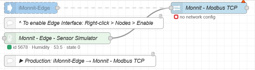
This tab turns Monnit sensor messages into a Modbus TCP server a PLC / SCADA can poll (same style of map as Monnit Ethernet Gateway 4).
Lab wiring: the green Monnit - Edge - Sensor Simulator feeds fake readings into Monnit - Modbus TCP.
Production: replace the simulator with iMonnit-Edge (see 03 iMonnit-Edge). Sensors must already be Online in the Edge UI (02 Path).
If you are new to Node-RED: you will open two dialogs — a shared Network config (the pencil), then the Monnit - Modbus TCP flow node. Deploy after changes so the listening port starts.
1. Big picture
  iMonnit-Edge (or Simulator)
        │  msg per sensor report
        ▼
  Monnit - Modbus TCP  ──TCP 502──►  PLC / mbpoll
- This node is a server. The PLC is the client — it connects and reads registers (it does not push sensor data into Node-RED).
- Map is read-only (Function Code 03 = Read Holding Registers).
- You cannot change sensor heartbeats over Modbus — use the Edge UI or BACnet writable points for that.
2. What is a “slot”?
Think of each sensor as one slot in a table the PLC reads:
| Slot | Holding registers (typical) | Holds |
|---|---|---|
| Gateway block | 40001 –40005 |
Gateway id / slot count style header |
| Slot 1 | 40101 … (16 regs) |
First sensor’s data words |
| Slot 2 | 40117 … |
Second sensor |
| … | +16 regs each | … |
Slot map (optional) pins a Monnit sensor id to a fixed slot so the PLC address never moves when you redeploy.
This lab pins humidity sensor 5678 → slot 1.
Leave the map empty → sensors fill slots in first-seen order (sticky until you Deploy again and the map rebuilds).
3. Network config (do this first)
Double-click Monnit - Modbus TCP → click the pencil beside Network.
That opens Monnit - Modbus Network (shared listen settings — not a separate wire on the canvas).
| Field | Suggested | Plain English |
|---|---|---|
| Name | e.g. Edge Modbus | Label in the config list |
| Port | 502 |
TCP port PLCs expect. If busy on the Edge, use 1502 and tell the PLC |
| Bind | 0.0.0.0 |
Listen on all NICs, or set the Edge LAN IP |
| Unit ID | 1 |
Modbus “slave” id — PLC must use the same number |
| Gateway ID | 0 or your id |
Optional 32-bit id → regs 40001 /40002 (EGW4-style) |
| Max slots | 50 |
How many sensors the map can hold |
| Data expire | 0 |
Seconds after last msg before data clears (0 = never) |
Click Update, then Deploy so the port is actually listening.
4. Monnit - Modbus TCP node
Double-click the flow node after the Network is saved.
| Field | What to do |
|---|---|
| Name | Canvas label (this lab: Monnit - Modbus TCP) |
| Network | Select the config from §3 |
| Slot map | Optional rows: Monnit sensor id → slot number |
| + add | Pin an important sensor to a fixed slot |
| Download CSV | After sensors have reported — hand the file to the PLC programmer |
Slot map tips
- Deploy so traffic is flowing (simulator or iMonnit-Edge)
- Open the node → + add (or edit the existing row)
- Set sensor id (e.g.
5678) and slot (1= first sensor block at 40101) - Done → Deploy again
5. Walk-through (do this on the lab tab)
- Deploy this tab — node status should show something like
:502 · N slots(green / listening) - Open the right sidebar → Debug — Modbus updates should tick when the simulator reports
- Double-click Monnit - Modbus TCP → confirm Network and the slot row for
5678→ slot1 - Optional: Download CSV and open it — that is the map your PLC team needs
- From a PC on the same LAN, poll with mbpoll (or your PLC):
mbpoll -m tcp -a 1 -r 1 -c 5 -t 3 -p 502 <EDGE_IP>
(-a 1 = Unit ID 1, -p 502 = port — change if you used 1502)
- Or open 09 Status → Modbus card → Copy test
Production cutover
- Delete or disconnect the simulator
- Wire iMonnit-Edge → Monnit - Modbus TCP
- Confirm sensors Online in Edge UI → Deploy
- Pin critical sensors in the slot map → Deploy → give CSV to the PLC programmer
6. Confirm & common issues
| Check | What “good” looks like |
|---|---|
| Node status | Listening on your port with a slot count (not a red error) |
| Debug | Modbus updates shows activity when sensors report |
| mbpoll / PLC | Reads succeed; values change when sensors update |
| 09 Status | Modbus RUNNING + Test Received after a Copy test |
Common issues
- Connection refused — not Deployed, wrong port, firewall, or Bind IP not reachable from the PLC PC
- Wrong / zero data — Unit ID mismatch, reading the wrong register range, or no sensor messages wired in yet
- Slot jumped after Deploy — pin that sensor in the Slot map
- Port already in use — change Network Port to
1502(or free 502)
7. Next
When Modbus reads look right, continue to 08 MQTT or use 09 Status for a support-style Modbus test without a full PLC.