ALTA MultiStage Thermostat Configuration and Installation Guide
Overview
The Monnit ALTA® MultiStage Thermostat controls conventional, heat pump, and dual fuel HVAC systems with up to three heating stages and two cooling stages. It features an integrated motion sensor to auto-detect when an area or room is occupied and enter an energy-saving state when they're not.
The thermostat is intrinsically tamper-proof since you can only control it via our password-protected iMonnit cloud-based platform. This prevents adjustments by unauthorized parties. The simple front panel interface provides mode and status information via multicolor LEDs.
Thermostat Connections
It's paramount to understand the process of connecting the ALTA MultiStage Thermostat, as improper connections often lead to issues. Referencing the detailed images below will make it easier to understand the corresponding function of each pin, aiding in proper setup and troubleshooting.


Enable Setting Changes—Jumper
The ALTA MultiStage Thermostat ships ready to configure. However, there is a lockout jumper that can prevent users from modifying the thermostat's settings. You can't change the settings if this jumper is on both pins. Remove the jumper to configure the settings.

Thermostat Logic
The thermostat has an integrated motion sensor, allowing you to regulate HVAC systems according to occupancy status. It enables the thermostat to adjust temperature settings dynamically based on whether the space is occupied or unoccupied. While the integrated motion sensor autonomously triggers changes in the thermostat's behavior based on detected activity, you can manually initiate occupied and unoccupied states as needed.
The iMonnit Dashboard

Within iMonnit, you can easily adjust the Occupied and Unoccupied State settings, initiate preferred states manually, or manage the HVAC fan control directly from the thermostat's Dashboard. This interface allows you to customize your thermostat settings according to occupant preferences and comfort needs.


- Dial Indicator: Indicates the Setpoint for the Occupied state and Cooling/Heating thresholds for the Unoccupied state.
- Setpoint Adjustment: Used to change the Setpoint for the Occupied state or the Cooling/Heating thresholds of the Occupied state by typing in the desired number or selecting + or -.
- Fan Control:
- Turn the fan Off
- On for 20 minutes
- On for 1 Hour
- On for 4 Hours
- Force Occupancy State: Can force to be Occupied or Unoccupied for a set duration.
- 20 minutes
- 1 hour
- 4 hours
- Heat/Cool Mode: Changes the operating mode of the thermostat.
- Heat
- Cool
- Auto
- Off
LED Status
To verify that your ALTA MultiStage Thermostat is operational and communicating effectively, check the LEDs. The Power (Pwr) and Radio Frequency (RF) LEDs should be illuminated, indicating that the thermostat is powered on and connected to the gateway. Additional LEDs will activate depending on the current functionality of the Thermostat.
For instance, the corresponding LED is lit if the heating function is active. This principle applies to all other functionalities of the thermostat, with each LED signaling the status of its respective function. Checking these LEDs provides a quick and reliable method to confirm the proper operation of your thermostat.

Settings to Configure
System Type
Sets the HVAC system type and what items are controlled. The HVAC system must be defined before use. If not, as a safety feature, no HVAC controls will turn on.
Heat/Cool Mode
Sets whether the thermostat automatically controls heating, cooling, emergency heat, or heating/cooling. Emergency heat is an option on select HVAC systems, bypassing the primary heating system to only use the emergency/aux heating system as the primary.
Temperature Buffer
Used with the set points to determine at which temperature the heating or cooling systems are activated. Example: If the set point is 70°F and the buffer is set to 5°, the heat will turn on at 65°F and off at 70°F. The thermostat doesn't turn off at the exact set point. It overshoots by 0.25°C to improve comfort and system efficiency.
Occupied Set Point
The temperature at which the heating and cooling systems turn off after they are activated. The thermostat doesn't turn off at this exact set point. It overshoots by 0.25°C to improve comfort and system efficiency.
Occupied Timeout
The amount of time after the occupied state has been triggered that the system will revert to the unoccupied temperature settings.
Unoccupied Heating and Cooling Set Points
The temperature at which the heating and cooling systems turn off after they are active. The thermostat doesn't turn off at this exact set point. It overshoots by 0.25°C to improve comfort and system efficiency.
Heating and Cooling Activation Time
The time the first stage is allowed to run before activating the stage associated with this configuration.
Heating and Cooling Activation Threshold
If the temperature exceeds the set point by this amount, the stage associated with this configuration will be activated immediately.
Stage Load Balancing
When on, this setting balances the load between the first and second stage heating or cooling, ensuring they run approximately the same time overall. This only applies when the System Type has two or more stages for heating or cooling. When turning the heater or cooling on, this checks the time tally for each stage and will turn on whichever stage has the lowest total runtime first.
The Stage Load Balancing setting should only be enabled when the first and second stages have close to the same heating or cooling capacity. If you're unsure about this setting, leave it OFF.
Reversing Valve Control
Defines whether the reversing valve is energized to cool or energized to heat. If Undefined, the heating/cooling system will not activate.
Show Advanced Settings
Allows for more advanced editing of the thermostat if set to show.
Aware when Occupied
If turned on, the thermostat will report Aware when motion is detected. The Occupied Timeout configuration acts as a rearm period for reporting motion.
Aware On State Change
If On, when the thermostat reports a state change, it will mark that data message as Aware.
The thermostat reports all state changes no matter what. If marked Aware, the message will force the gateway to send that data to the server immediately if the gateway is also set to transmit Aware messages immediately.
Fan Control Mode
This sets various control states for the fan.
• Auto: The HVAC system, not the thermostat, controls the fan.
• Auto+Periodic: Enable configuration to turn the fan on for a period at the beginning of a longer period. It is meant to be used with Fan Period and Fan Interval configurations. If a cooling or heating event occurs, the Periodic Fan event time is reset.
• On: The fan is always on with this setting.
• Active Fan Control: The thermostat actively controls when the fan turns on/off when the heating/cooling starts and stops. It is meant to be used with the various Fan Start Time configurations.
• Off: The HVAC system controls the fan during heating and cooling, not the thermostat.
Fan On Period
The amount of time the fan is forced on during the Fan Interval. Example: Fan On Period = 10 minutes, Fan Interval = 120 minutes. At the beginning of the 120-minute Fan Interval, the fan will be forced on for 10 minutes. After 10 minutes, the fan will turn off. Then, 120 minutes after the fan was forced on, the fan will be forced on again. The Fan On Period must be less than the Fan Auto Period.
Fan Interval
The time inside which the Fan On Period operates. The Fan Interval must be greater than the Fan On Period.
Fan Start Time For Heater
The time the fan starts before(-)/after(+) the heater starts.
Fan Stop Time For Heater
The time the fan stops before(-)/after(+) the heater stops.
Fan Start Delay For Cooler
The time the fan starts before(-)/after(+) the cooler starts.
Fan Stop Delay For Cooler
The time the fan stops before(-)/after(+) the cooler stops.
Calibration/Controls
Fan Override
Turns the fan on for a set period.
Occupancy Override
This command will force the thermostat to enter the occupied state and use the Occupied Temperature settings for a selected duration.
Unoccupied Override
This command forces the thermostat to enter the unoccupied state and use the Unoccupied Temperature settings for the selected duration.
Temperature Offset
Adjusts temperature readings by the Offset Value. Example: An offset of 2°C will change a 20°C reading to a 22°C.
Humidity Offset
Adjusts humidity readings by the Offset Value. Example: An offset of 2% will change a 20% reading to a 22%. It has no effect if the humidity hardware option isn't installed.
Additional Features and Options
Other settings, such as Scale and Calibration, may appear on their page.
Scale

Show temperature values in Fahrenheit or Celsius.
Calibration

Calibrate Fan Override, Occupancy Override, and Unoccupancy Override.
Temperature Offset and Humidity Offset
This refers to the variance between the actual temperature and the temperature reported by the device. When setting an offset, the objective is to align the thermostat readings with another device's, ensuring consistency and accuracy across measurements.
Installation Steps
If this is your first time setting up your Monnit system, you must set up your iMonnit account and connect your ALTA Gateway to iMonnit before registering your thermostat. See this article for steps to start: Creating an iMonnit account.
Step 1.
Remove the thermostat from the package.
Step 2.
Register the thermostat in iMonnit. Set up the thermostat in iMonnit before wiring.
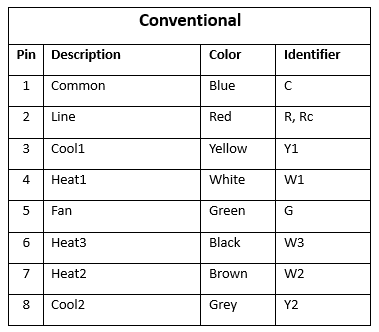
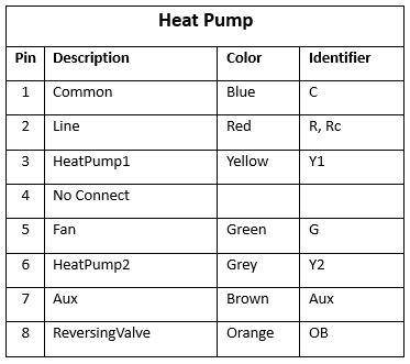
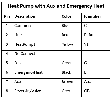
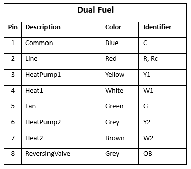
Step 3.—Wiring Guide
Refer to the tables below for wiring the thermostat to different system types.
Warning: The wiring colors referenced are standard colors used to wire the indicated system type. However, that doesn't guarantee the colors match exactly with your system. The best approach is to reference how the previous working thermostat was wired and match the identifiers in the tables below with those on the previous thermostat. We recommend having a professional install the thermostat if the wires aren't labeled with identifiers for new installations.
Separate the thermostat front from the back mounting plate. Feed the wires through the mounting plate and wire them based on your system type. Mount the plate to the wall with the provided hardware.
Step 4.
Mount the thermostat front to the back plate. The LEDs should illuminate, indicating the system has power. Refer to the LED Behavior Descriptions section below for more information on what the LEDs mean.
Step 5.
Verify the thermostat communicates with the intended gateway and has good signal strength via iMonnit.
Step 6.
Perform additional tests through iMonnit as desired to ensure appropriate functionality for your application.
LED Behavior Descriptions
